V1.16 - 04.04.2014 09:33
DiSIM New SIM Card Server (nSCS)
6.
SIM Card Server settings group
Automatic
configuration and status (application software)
Hardware
/ Functional Characteristics
Overview
nSCS is a single-board device featuring an Ethernet up-link
connection, a local processing module and up to 32 SIM Card Holders in three
layout mixes:
-
16
Holders available at board edge (hot-pluggable SIM Cards)
-
16
Holders at board edge + 16 internal Holders
-
32
internal Holders
An USB Service Interface is also available for management,
debugging and service.
The board powers from a single 5Vdc supply and spans over a
single Eurocard Rack slot (6U height).
Regardless of the SIM Holders layout, the nSCS device can be
used as a stand-alone SIM Card Server (SCS) or as part of an extended Virtual
SIM Card Server (vSCS).
Stand-alone nSCS deployment
In stand-alone mode, the nSCS needs only an Ethernet
connection (possibly shared with other nSCS devices through an Ethernet switch)
and a gateway / router or direct connection to a public network accessible to
clients.
Note: Direct
connection of nSCS devices to a public network (Internet) is strongly
discouraged because of potential security vulnerability. Internal nSCS
processing module has a minimal TCP/IP stack with weak support for security and
packet filtering options. Use of a filter / router and / or a firewall between
the nSCS device(s) and public networks would minimize
the risk of attacks and undesired access (flooding).
Stand-alone mode is fully compatible with existing SIM Card
Servers, with only a maximum of 32 SIM Card Holders available per server
instead of 48. All functional commands are processed by the internal unit
without the need of any other external hardware or software.
Compatibility with the first version (v1) of SIM Card Server
and some management and configuration commands has been removed, but the
complete v2 functional compatibility is guaranteed.
Minimal SOAP support and HTTP Server are implemented and
ready to be used by SCS v2 clients.
In this mode, the DiSIM nSCS device
is a direct, 1:1 replacement for existing DiSIM SCS
installations.
Note: Please be aware
that traditional SCS v2 clients cannot handle the concept of hot pluggable SIM
Cards. So when using the nSCS as a replacement for existing DiSIM
SCS installations, handle the insertion / removal of SIM Cards with extreme
care (close connections first, frequently refresh inserted SIM Cards list,
etc).
To use nSCS in stand-alone mode, the only needed
configuration settings are:
-
a
static IP Address and TCP listening port for the SCServer
-
an
additional TCP port for SOAP / UPnP Server (if used)
Note: Care must be
taken when configuring multiple nSCServers on the
same internal subnet to be used by v2 clients. Traditional SCS v2 clients
(SCESupport.dll) can handle only a single server per IP address (regardless of
assigned port number).
If a front-end router
/ gateway is able to identify hosts based on MAC
Address and / or Hostname and route / NAT packets to designated nSCServer based on symbolic names, DHCP can be enabled for
automatic IP Address assignment. But a single nSCS will be available to
traditional SCS v2 clients on the external (public) IP address.
The DHCP Server may also
be instructed to assign specific settings to nSCS DHCP Clients, based on
reported MAC (Ethernet Address), Hostname and Vendor Class Identifier.
Configuration parameters (addresses, timeouts, access control,
etc.) that apply to SCS v2 can be set using global configuration pages or DHCP
Server.
The Logging section can be enabled and used, independently
of the SCServer v2 compatibility mode.
nSCS Hardware Description
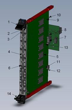 The nSCS
board diagram is presented in figure:
The nSCS
board diagram is presented in figure:
- Front-panel
upper handle
- Service
Processor LED
- Main
Processor LED
- Front-panel
SIM Holders
- Internal
SIM Holders
- Front-panel
SIM Holder LEDs
- Backplane
connector (power supply, Ethernet)
- Ethernet
LEDs
- Board
power supply regulator
- Power
LED
- Service
Interface processor
- USB
Connection LED
- Main
Processor
- Front
panel lower handle (with switch)
To insert the nSCS board into the rack follow next steps:
-
Place
the board in vertical position with SP/MP LEDs
upward;
-
Select
a position in rack and slide the board along the red guiding rails. Be sure to
match the upper/lower rail position so that the board is vertical;
-
The
upper/lower front-panel handles must be in the “open” position (outward);
Note: The small screw in the handle may
sometimes prevent the handle (hook) to fully open. When this happens, please
push the screw inside to let the hook open completely.
-
Align
the hook claws with the perforations in the upper/lower edges of the rack. The
claws must properly engage in those perforations (slightly move the front-panel
left/right to find the right position).
-
Gently
close the front panel hooks (inward position). The white button in the middle
of the handle should click when fully closed. The nSCS board should now be
properly engaged with the backplane connector.
When the lower front-panel handle is fully closed, the
micro-switch inside the handle will signal the board that operating conditions
are met and it can start running.
To remove the nSCS board from the rack, first push the white
button in the lower front-panel handle. The micro-switch will signal a software
reset to the board which will stop running in a few seconds.
Then push the white button in the upper front-panel handle
and open the handles (outward). The board will disengage from backplane connector
and upper/lower edges of the rack. Pull the board outside the rack along the
guide rails.
Note: The little screw
inside the front-panel handles can be used to permanently fix the board inside
the rack. Be sure to unscrew them first, before attempting to remove the board
from rack.
nSCS Functional Description
Once the nSCS board is inserted into the rack and 5Vdc
supply is present, the device is ready to run.
First the Service Processor (SP) wakes-up and begins a
series of hardware and firmware self-tests. During this time, the SP LED on the
front-panel will light Red. This stage should take only a few milliseconds.
If everything is in order, the SP LED color turns
Note: The Service
Processor can be powered by the board 5Vdc supply or through USB connection.
Thus SP can run without powering the rest of the board. This mode is intended
for factory / debugging service and should not be used during normal operation
(disconnect USB cable before powering the board).
While operating conditions are not met (5Vdc supply absent
or outside allowed range and/or front-panel lower handle switch is open), the
Service Processor will hold the rest of the board in Reset, with board power
turned Off. The SP LED on the front-panel will flash
When 5Vdc supply is present and stable, Power LED will turn
Green. If the handle switch is also closed, SP will turn On
the board power (Power LED lights
SP will continue to monitor operating conditions and signal
(software) to MP any alarms. MP is responsible to reset Holder Processors and
himself, returning to initial operating state (driven by SP) when done.
When Main Processor starts running, it will also perform
first some hardware and firmware self-testing. During this time the MP LED on
the front panel will light Red and the step should complete in a fraction of a
second.
If MP remains in this initial step with LED Red, the board
is facing unrecoverable hardware or firmware errors and must be diagnosed
through the Service Interface (USB).
Note: Some firmware
errors can be recovered automatically. MP is able to reprogram the Base
firmware from a backup copy saved internally. This may last for a few seconds
and should not be considered a permanent error.
DO NOT TURN OFF the
board power during this time.
A permanent error
should be considered only if no activity is performed by MP during 10 or more
seconds.
If internal tests complete with success, MP LED on the
front-panel will turn
Next step is to activate the Ethernet connection. Without a
proper network connection, MP will remain in this stage indefinitely.
Note: The entire
purpose of the SIM Card Server is to offer network services to clients. Also
the one and standard access point to the device is the network interface. Thus
no activity can be performed without a proper network connection and the entire
system sleeps in an idle state.
Once the Ethernet link is available, DHCP configuration
process starts (see nSCS Configuration
for more details).
Next stage is to search for firmware update if Automatic Updates are enabled. MP will
contact the designated Update Server
and request updates for current firmware versions running on different
processors on the nSCS board (Service, Main Base, Main System and Holders). If
an update for any of those is available, it will be downloaded and applied. The
board will then Reset/Restart and the process will repeat until all firmware
parts are synchronized with the firmware images stored on the Update Server.
Note: When new
firmware releases are found on the Update Server, it is possible for this boot
stage to last for significant periods of time. During this time the board may
seem to behave heretically, with LEDs flashing Red
and network connection going up and down repeatedly.
For example,
reprogramming Holder Processors may last up to one minute on a 32 Holders board.
Don’t panic and let
the system do the job. It is normal and the update phase will eventually end.
It is an error only if the system seems to hang-up in the same state for a long
period of time (minutes). Logging is available and update errors can be
detected by inspecting the log files.
After the update phase completes with network link up and no
other updates to be downloaded, a final suite of tests is performed on the
complete system and SIM Holders. Results of those tests are not preventing the device
to function as a whole. Errors for specific services or holders will only
disable functionality of the offending section without affecting the rest.
Services will log the error (or fail to log the normal operating start) and HP LEDs on the front-panel may turn Red and remain like that.
The normal operating state of the nSCS device is indicated
by the MP front-panel LED turning Green and flashing regularly each second. SP
LED is Green from a previous stage and Ethernet LEDs are
On, depending on link parameters.
HP LEDs on the front panel will light
This normal operating state can be interrupted by a number
of events.
First, SP can signal a power failure or front-panel switch
opening. When this happens, MP will notify all child services and processors,
close pending connections, deactivate the Ethernet adapter and go into initial
state. On power failure events, MP will auto-Reset (software) and pass control
over to the SP.
Tip: It is possible to
use the lower handle on the front-panel (micro-switch) as software reset of the
nSCS device. The entire device is placed in a stand-by position and SIM Cards
can be safely inserted or removed if client software is not able to deal with
hot-plugging.
Also the complete device
initialization stages are repeated, possibly recovering from errors and
hang-ups.
Reset/Restart commands can also be submitted over Telnet,
Web or Service Interface. Again, the device shuts down and initialization is
repeated (see respective sections for more details).
Finally, network connection failures will stop all services
and holder processors and the device will enter a stand-by state until network
link is back up.
Scanning for updates is repeated automatically at specific
intervals in background. If new firmware versions are detected during normal
system operation, they will only be logged without interrupting functionality. When
network connection drops or the system is Reset/Restarted, pending updates are
applied automatically (if enabled) before normal device operation resumes.
Summary of LED
indication:
Power LED states:
|
Shut |
Board power (5Vdc) not present |
|
Green, steady |
5Vdc power supplied to board |
|
Orange, steady |
3V3 board power (on-board regulator) On |
Ethernet LEDs states:
|
Shut |
No connection |
|
Green |
Connected 10BASE-T |
|
|
Connected 100BASE-TX |
|
Flashing (Green or |
Link activity (Rx/Tx) |
Second Ethernet LED (board back):
|
Shut |
Half-duplex link |
|
Flashing |
Collision (half-duplex only) |
|
Green, steady |
Full-duplex link |
USB LED states:
|
Shut |
USB not connected |
|
Green, steady |
USB connected, no host application |
|
Orange, steady |
USB connected, Service/Test/Debug mode |
|
Green or |
USB Suspend state |
SP LED states:
|
Shut |
Board/SP not powered |
|
Red, steady |
SP internal error |
|
Orange, flashing |
No board power, holder switch open |
|
Orange, steady |
Testing / starting MP |
|
Green |
Normal operation |
|
Other |
Intermediate upgrade stages or hang-up (bug, please report) |
MP LED states:
|
Shut |
Not powered |
|
Red, steady |
MP internal error |
|
Orange, steady |
No network |
|
Green |
MPBase running (testing, upgrading, etc) |
|
Green, flashing |
MPSystem running (normal operation) |
|
Other |
Intermediate upgrade stages or hang-up (bug, please report) |
Important: If MP LED stops flashing during normal operation
(either steady Green or shut) please turn off the board power or disconnect the
network link. This may be a network hang-up and the nSCS
device may flood the local network with garbage Ethernet packets.
(Please see dedicated section for Holder Processors functional
description).
nSCS Configuration
nSCS devices need a minimal
configuration before being able to run.
There are four levels of internal configuration storage,
explained bellow.
- Layer1
– non-volatile EEPROM for permanent storage of configuration settings. This
area is empty on new devices meaning to use build defaults for all
configurable parameters;
- Layer2
– RAM copy of entire EEPROM content. Because the slow access time of
EEPROM, a second storage area is allocated in internal RAM. Copy from Layer1
to Layer2 is performed automatically after each boot;
- Layer3
– this is another RAM area initialized by DHCP service before network
configuration. Layer2 configuration is copied here,
then build defaults are set for all parameters not defined in permanent configuration.
This step is performed each time the network connection goes up, even if
DHCP client will not run or a DHCP
Server is not configured or available;
- Layer4
– is the complete (operational) configuration resulted by applying
settings received from DHCP Server
(if any) to the default configuration build in Layer3;
After completing the last step (Layer4) internal services
and processing modules are allowed to run. Layer3 and Layer4 configuration are
discarded each time the network connection is down (services and processing
modules are stopped) and rebuild when network connection is up again.
Changing configuration settings can be performed over
various interfaces (Web, Telnet and Console) and operates on Layer2. In order
for those changes to take effect, a Network
Reset or System Restart (without Reboot) is needed. A good practice would
be to change configuration parameters in Layer2 then test system operation. If
everything works as expected, changes can be made permanent by storing Layer2
to Layer1 (EEPROM).
Minimal configuration that allows the device to operate must
define the IP layer parameters. There are build defaults for mandatory
parameters and an IP address can be automatically generated. Other internal
services can be stopped/not functional by default or running with default
parameters.
The IP address and Subnet Mask can be set from permanent
(stored) configuration, using a DHCP Server or auto-generated in the “local
link” address space (169.254.x.y).
If a DHCP Server
is available in the local subnet, the complete configuration can be set or
modified. Some configuration options conform to the DHCP standard, other are
vendor extensions. The name for the vendor class is DISIM.nSCS10 and the DHCP
Server can be instructed to respond with vendor options to devices that
advertise in this class (see an example in Annex A).
Configurable parameters are grouped in several sections. For
each group it is possible to apply different methods of handling configuration:
- Use Configured – this method apply by default to all groups.
When this method is allowed for a group, the configured values from Layer2
are used to build Layer3. If this method is not allowed, settings in
Layer2 are ignored and Layer3 is either left not set or filled with build
defaults for mandatory parameters.
- Use DHCP – this method apply by default to all groups. When
this method is allowed for a group, the settings received in response from
a DHCP Server will override
existing settings (in Layer4). If no DHCP
Server is available or no response is received or the received
response does not contain the relevant parameter option, the value is left
as initialized in Layer3. If this method is not allowed, the DHCP client will
not request parameters in that group and received options for those
parameters (if any) are ignored.
As a practical conclusion, when both methods are allowed
(the default case), configured values are used where present, build defaults
are filled where needed, then DHCP service overrides any of them based on the
options received from a DHCP Server.
When Use Configured is not allowed, only build defaults and
maybe DHCP options are used to build Layer3 and Layer4 of configuration.
If none is allowed, the processing module or service that
depends on that parameter group is left unconfigurated
and thus not running. The only exception is the IP layer which is configured
with an auto-generated address (local link space) and default parameters to
make the device available on the network with limited functionality for
possible reconfiguration.
Use Configured method can be disabled to
completely ignore a group of parameters already stored in configuration without
the need to delete them individually. The function will relay on DHCP options
(if Use DHCP is enabled and relevant
options are received) or will not operate at all. Enabling the service later
with pre-configured parameters will only take one click.
A preferred DHCP
Server can be preset in configuration. If set, the first attempt to
retrieve configuration parameters will be addressed to that server (unicast). If the server fails to respond (after multiple
retries), the normal broadcasting method is applied to search for other
available DHCP servers. Subsequent messages exchange with the DHCP Server will use the address of the
first one to respond, either preset or discovered by broadcast.
The list of configurable parameters for the nSCS device is
presented bellow:
1. LAN settings group
IP Address
Standard DHCP
Build default:
auto-generated in local-link address space (169.254.x.y)
Address to be used (Configured, DHCP or auto-generated) is
verified with ARP probes. If address fails the test, a new request is sent to
DHCP server or another random address is generated. Auto-generated mode is the
fall-back if any other method fails or is not available.
Note: once an IP address
is auto-generated and verified, the configuration process ends and the device
starts operating. Even if a DHCP Server becomes available at a later time, the device
will not attempt to reconfigure itself. A Network Reset is needed in order to
restart the configuration process.
Subnet Mask
Standard DHCP option 1
Build default:
255.255.0.0 with local-link IP address
Broadcast Address
Standard DHCP option 28
Build default: IP
Address OR complemented Subnet Mask
ARP Timeout
Standard DHCP option
35
Build default: 20
minutes
IP Time-To-Live
Standard DHCP option
23
Build default: 64
TCP Time-To-Live
Standard DHCP option
37
Build default: 40
DNS Servers (up to 3)
Standard DHCP option 6
Build default: none
Current firmware version does not use DNS to resolve host
names. There is no processing module or service that needs to resolve remote
machine names and all configuration parameters involving external machines are
set using the IP address and not the DNS name. For this reason a DNS client is
not implemented and this configuration parameter is ignored.
Domain Name
Standard DHCP option
15
Build default: no name
Classless Routes
(Almost)Standard DHCP
option 121
Build default: none
Under testing. Please do not use for the moment
(ignored).
Gateway
Standard DHCP option 3
Build default: none
When not defined, connections can be made only in the local
subnet.
Please define and allow external connections to the Update Server.
Static Routes
Standard DHCP option
33
Build default: none
Under testing. Please do not use for the moment
(ignored).
2. Time settings group
Time Server
Standard DHCP option 4
Build default: none
Current firmware version is not using a Time Server
connection as fall-back for Real Time Clock synchronization. Only NTP Server
options are available. Please do not use (ignored).
NTP Server
Standard DHCP option
42
Build default: none
Listen to NTP
Broadcasts
Vendor option 1
Build default: yes
The device needs to synchronize the internal Real Time Clock
from an external source because there is no battery backup. Every time the device
is rebooted the internal clock starts from zero UTC (01.01.1970 00:00:00). A
good time source is required mainly for logging timestamps.
If no time source is available, the messages timestamp will
reflect the Time-Since-Boot.
Note: the precision of
internal clock is better than 50ppm which could lead to a drift of up to 5
seconds per day. Periodic clock adjustment using a NTP Server is recommended
for long term, unattended running. Using a broadcasting
NTP Server in the local subnet (roughly once every minute) can synchronize
automatically a large number of devices.
3. Logging settings group
Log Server
Standard DHCP option 7
Build default: none
(no logging)
Vendor option 9
Build default: 514
(UDP)
Log Facility
Vendor option 10
Build default: 16
(Local0)
Log Level
Vendor option 11
Build default: 3 (Info)
Log Level values are slightly different from standard to
allow multiple debugging levels (see nSCS Logging
section for details).
4. Update settings group
Enable Automatic Updates
Vendor option 8
Build default: no
Update Server
Standard DHCP option
72(*see Note)
Build default:
update.disim.org (86.34.19.60)
Standard DHCP option 72 refers to “WWW Server” and it is
used as Update Server address simply
because updates are stored on the same server (www.disim.org). The name
(update.disim.org) is hard-wired to a static address because there is no DNS
client implemented.
However this parameter is configurable to allow redefinition
of the update store. In large implementations it is advisable to maintain a
local copy of update files in order to allow unnecessary external network
traffic from each device (see nSCS Firmware Update
for more details).
Vendor option 12
Build default: 80
(http)
5. UPnP settings group
UPnP Enable
Vendor option 2
Build default: yes
The UPnP Server contains two parts: the UPnP advertise /
discovery mechanism using multicast UDP messages and a HTTP Server responding
to requests from clients.
This HTTP Server is shared between UPnP infrastructure and
SOAP support (see bellow) and is enabled if any of those services is active.
This flag (UPnP Enable)
controls the UPnP service: enabled means UPnP multicast engine + HTTP Server.
Tip: If enabled, the
UPnP service can be used to discover the IP address currently used by the device
(for example when auto-generated) by inspecting the “Presentation” field in NOTIFY
messages.
SOAP/UPnP Server Port
Vendor option 13
Build default: random
or 17117 (*see Note)
When only the UPnP
Server is enabled, the port for the associated HTTP Server is configured
randomly. Please note that the main HTTP Server implemented on device is always
responding to standard port 80. This parameter cannot be set to this value
(80).
If SOAP Support is
enabled (see bellow) the default port for the SOAP/UPnP Server is 17117 and can
be changed to another value using this parameter.
UPnP Time-To-Live
Vendor option 14
Build default: 4
Set this parameter to the required number of routers / gateways
the UPnP announcements must traverse in order to reach all potential clients.
In auto-generated IP Address mode (local-link) this
parameter is automatically set to 1 (local subnet only).
6. SIM Card Server settings group
SIM Card Server Enable
Vendor option 3
Build default: yes
Enable SIM Card Server functionality of the device.
SIM Card Server UDP Enable
Vendor option 4
Build default: no
Under testing. Please do not use for the moment
(ignored).
Vendor option 21
Build default: 7117
Port number used for both TCP and UDP connections from SCS
clients.
SIM Card Server Connection
Timeout
Vendor option 22
Build default: 0
(disabled)
SIM Card Server can close client connections that are
inactive for this interval.
Allowed value for this parameter is in the range of 300..43200 seconds (5 minutes to 12 hours).
Zero means the function is disabled.
SIM Card Server Keepalive Interval
Vendor option 23
Build default: 0
(disabled)
SIM Card Server can send void packets at specified interval
over a client connection to test if still active. After a number of probes
without response, when Connection Timeout
limit is reached, the client connection is closed.
Allowed value for this parameter is in the range of 60..3600 seconds (1 minute to 1 hour).
Zero means the function is disabled.
SOAP Server Enable
Vendor option 5
Build default: yes
SOAP Server cannot be enabled unless the SIM Card Server is
also enabled.
See SOAP/UPnP Server Port parameter for details about
associated HTTP Server port.
Web page configuration
The nSCS device Web page is
available at http://<ip address>/
The configuration parameters currently used by the device
(Layer4) are shown in menu section Status
/ Settings.
The Configuration
menu section is dedicated to configuring the device. Configuration parameters
groups are available in separate pages (LAN, Time, Log, etc.).
In each configuration page, the first row shows action
buttons used to send configuration requests to the nSCS
device.
Refresh – reload configuration parameters in all sections from
device (last Saved values).
Save – save configuration values in all sections that are modified
since last Save / Refresh.
Because Refresh and Save act
globally on all configuration groups (sections) it is possible to navigate
between pages and make modifications in any section before saving them to the
device. Leaving a configuration page (section) will not loose the changes made
there.
Defaults – reset all configuration parameters to factory
defaults (all empty / not set, Use DHCP enabled).
Store – save modifications in non-volatile EEPROM (Layer2 to
Layer1). This action is queued internally in the device and will be executed in
the first available time slot. It will usually take less than one second and
only a power failure during this time may prevent completion. At all times
there is a backup copy of the entire Layer1 configuration so even if the
storing process fails to complete, the device will still be usable with the
last Stored
configuration parameters.
Note: Actions that
change configuration settings (Save, Defaults and Store) are protected by a
password (see Access Protection for more details).
Network Reset – force a network down – up sequence. The device will close
all connections (including the Web page client) and will reset the network
adapter for about 5 seconds. When network is back up, the internal
configuration sequence is performed, using currently saved values.
Tip: change
configuration parameters as needed and Save
them. Then apply a Network Reset.
The device will restart with Saved configuration settings (Layer2 in RAM). It
is then possible to check if desired operating mode is performed and finally Store in non-volatile EEPROM (Layer1).
Automatic configuration and status (application software)
Configurable parameters of nSCS
devices and configuration operations can be performed without manual
interaction in the Web page by using scripts or software applications. The only
requirement for such a script or application is to be able to send HTTP GET requests to the device IP
Address and parse the received response.
Example HTTP Request (TCP packet to device IP Address, port
80):
GET <URI> HTTP/1.1
Host: <ip_address>
User Agent: ...
Example HTTP Response:
HTTP/1.1 200 OK
Date: Mon, 04 Nov 2013 15:36:33 GMT
Server: nSCS-HTTPServer/0.20.104
Content-Type: text/plain; charset=utf-8Content-Length: ...
<response_body>
Following table shows some possible values for the URI
parameter of the GET request.
|
URI |
Response Status |
Response Body |
Action |
|
/Configuration |
200 OK |
list of nSCS_... configuration parameters |
Refresh |
|
/Configuration/Set?query_string |
200 OK |
list of nSCS_... configuration parameters |
Save |
|
/Configuration/Reset |
200 OK |
list of nSCS_... configuration parameters |
Defaults |
|
/Configuration/Store |
204 No
Content |
None |
Store |
|
/Manage/NetReset |
204 No
Content |
None |
Network Reset |
Note: The “206 Partial
Content” response status is used to indicate that some parameters are set,
other encountered errors (for example invalid name or value). The returned list
contains actual parameter values. Compare the sent query string with returned
values to locate possible errors.
The query string passed for the Configuration Save action is build the usual way:
/Configuration/Set?parameter1=value1¶meter2=value2&...
Accepted values
are 0 / 1 for boolean
variables and strings for all other parameters. Strings can be empty to set the
associated parameter to “undefined” (use default).
There is no need to send a complete list of parameters with
each request: only those who change value should be included in the query
string.
The parameter list returned in the HTTP Response body
contains all parameter=value
pairs, one per line.
To find accepted parameter
names, please send a Refresh request
(/Configuration) and inspect the
returned list.
Note that further versions may add new configurable parameters
to the list, but names of existing parameters will never change.
Access Protection
Client connections to the Telnet and HTTP Servers provided
by nSCS devices may sometimes require Authentication
before proceeding.
For example, requests sent by the Web page (browser) or
controlling application that could modify configuration settings or change the
device operating mode are set to require prior authorization. Telnet sessions
request a password to be entered (login) at the beginning.
nSCS devices provide a single user name
“Administrator” with an unique attached password. Care must be taken when
managing this password as it cannot be changed or reset unless it is known,
therefore all-or-nothing access rights are granted to clients.
The default (factory preset) password for the Administrator
is “admin”.
Authentication over Telnet is unsecure
because password is sent in plain text over the TCP connection and can be
easily sniffed with any network analyzer.
Therefore, avoid using Telnet connections from remote
clients unless absolutely necessary. Local subnet connections are supposed to
be protected by a firewall so there is less danger.
Regular browsers use two methods to handle Authentication
requests: Basic and Digest.
Basic method is sending a Username and a Password in plain
text so it’s of little use. Digest method requires the server (in this case the
nSCS device) to memorize a random piece of data for
each client and this cannot be implemented in nSCS.
The method used by nSCS is a
derivative of Digest. A “LocalKey” is randomly
generated after each boot and it’s shared by all clients. Based on this key and
the connection IP address the server generates a “SessionKey”
for each client. The browser responds with the hash of this key and the Password
entered by user (the “LoginKey”) and that is validated by the server.
The “LoginKey” could be sniffed
and reused by another client only if it connects from the same IP address and
it uses the key during the same nSCS session.
Therefore, after authenticating to use any of the protected
commands, it is a good practice to Restart/Reboot the nSCS
device in order to invalidate the “LocalKey” and thus
anything derived from it.
For controlling applications that want to pass commands to a nSCS device, the authentication
mechanism should be implemented as follows:
- Pass
a request to the server (nSCS device).
- If
the requested resource is protected, the server will respond with “401
Unauthorized”.
- In
the response header the server set a cookie “sessionkey=…”
with a 32 hex characters value
- Application
should hash using MD5 algorithm the following string:
hostnamepasswordsessionkey
where: hostname is the 15 characters nSCS device name (SCSyyyyww…)
password should be a UTF-8 encoded string of
4..15 characters
sessionkey is the binary block of 16 bytes parsed from the received
cookie
- Application
repeats the initial request (step 1) with a Cookie header containing the
received sessionkey and the computed loginkey.
- If
authentication pass, the server will respond with
the normal answer to the requested resource. If not, the server will
respond with “403 Forbidden” status.
- The
keys can be reused in subsequent requests without modification if sent
from the same IP address and during the same nSCS
session. If something changes during this time, the server will delete the
sent keys (cookies), generate a new sessionkey
and respond again with “401 Unauthorized” status. Client should regenerate
a loginkey based on the new sessionkey
and retry the request.
nSCS Logging
nSCS device is able to log a variety of
information to an external destination. Internally the device features a ring
buffer able to hold about 1000 messages. The buffer is flushed to the external
destination (Log Server or Console) when available. The logger will push a
“missed logs” message if the queue was forced to discard oldest messages to
make room for new ones. At any time, if a Log Server is configured or Console
connected over USB, the last log messages stored in internal buffer will be
received in a continuous stream.
Please beware of high
network traffic when configuration is changed during normal operation.
Logging to an external Log Server complies with the Syslog Protocol (RFC 5424). Log messages are sent using UDP
transport, to a configurable IP address and port.
The format of UDP packets is (only bolded sections are
variable):
<pri>1 yyyy-mm-ddThh:mm:ss.ffZ hostname appname
procid msgid – msg
where:
pri = Log Facility * 8 + Log Severity (decimal number)
yyyy, mm, dd, hh, mm, ss, ff = message timestamp as UTC time or time-since-boot, with 1/100
second resolution. Please note that this is the time the message was posted by
the processing module, not the time the packet was sent out. When mixing log messages
from multiple sources, if internal clocks are not perfectly synchronized,
received packets may not show timestamps in ascending order.
hostname is the nSCS device name (SCS…)
appname is name of the source of the log message. It can be:
MP the Main
processor
HPxx Holder xx processor
SP the
Service processor
procid is the name of the processing section inside the processor
that sourced the message (System, Ethernet, DHCP, Upgrade, SIM Card, etc.)
msgid is the message type number (EventId)
msg is a descriptive string generated internally based on msgid and attached parameters (if any).
Please note that some log
messages may not have a human readable description (for example debugging check
points). In this case the meaning of the message is defined by msgid and a list of hexadecimal numbers (the attached parameters).
The configurable Log Level defines the Severity of log
messages that are to be stored in the internal buffer. Only messages with
Severity equal or above the preset Log Level are stored in the internal buffer
(and then sent out). Messages of lower Severity are ignored (discarded).
The Log Level may be set to different values for MP, HP and
SP. At boot all use the configured or default Log Level. Changing the Log Level
for a single source allows a closer inspection of the operation of that source
without flooding the log buffer with messages from other sources.
However, the Log Level for a source is unique and shared by
all modules (procid)
so it is not possible to set different levels for processing subsections inside
that source. For example either all or none of received network packets can be
logged by MP Ethernet module. It is not possible to see only TCP traffic,
ignoring other packets or see DHCP errors only and debug information for the
Update module.
The Log Severity levels defined in Syslog
Protocol are slightly changed to allow more debugging levels.
0 – State Logs at any preset level (highest
priority) information about device operating state.
1 – Error Logs errors encountered in any
processing module. The error itself may not be relevant without operating
information (messages of lower severity) but it can be a sign something is
wrong and the Log Level can be raised to detect the operating stage that
triggers the error.
2 – Warning Logs messages signaling something
is not right but not fatal for the operation of the processing module.
3 – Info (default) Logs informative messages about
sequence and processing phase. Useful to locate the source of
Errors and Warnings.
4 – Debug Logs more detailed information
about processing phase.
5..7 – Debug1..Debug3 Logs even more detailed information
with sequence of bytes, packets content, etc. Please be sure to have a fast and
reliable log destination if using any of those levels because of the massive
amount of data.
There are numerous applications able to parse and display
Log messages conforming to Syslog Protocol. Linux
systems offer a built-in daemon for this purpose (see an example in Annex B).
nSCS Firmware Update
nSCS devices can perform automatic
firmware updates of processors firmware.
There are four firmware parts, each targeting a specific
processor on board. Firmware images are stored in files with extension .fuf
(Firmware Update File), a proprietary format.
At boot, network reset or periodic intervals, the nSCS device attempts to connect to an Update Server,
request the header of available update files, compare versions and (if needed)
download and install the update(s).
If the connection cannot be made or the files are missing, a complain will be logged but this is not a fatal error.
Please also note that Automatic Update is not performed
during normal operation of nSCS devices. If an update
is detected on server but the device is operating, only a message will be
logged. The update will be downloaded at a latter time, after next boot or
network reset and only if Automatic Updates are enabled. The reason for this
behavior is that updating firmware requires a device reset and that could
disturb normal device operation and active client connections.
By default, the address of the Update Server is hardwired in
firmware to “update.disim.org” HTTP Server.
For isolated or secured deployments of nSCS
devices, it is possible to configure an alternate IPAddress : Port for the Update
Server (see nSCS Update settings).
The HTTP Server responding to the configured address:port must be able to
handle GET requests with the Host request header set to update.disim.org (no DNS lookup) and
honor Range request header for
partial file downloads. The HTTP Server should not process the FUF file in any
sense and must send it in binary format. If needed, a MIME association should
be configured for the file extension .fuf to application/octet-stream.
The four update files searched by nSCS
devices on the Update Server are:
/nSCS/MPBase.fuf – update file for Main Processor
base firmware
/nSCS/MPSys-MM-mm.fuf – update file for Main Processor
application firmware
where MM and mm are the version numbers
of the compatible MPBase
firmware
/nSCS/SPSys.fuf – update file for Service Processor
firmware
/nSCS/HPSys.fuf – update file for Holder Processors
firmware
The reason for versioning the MPSys file name is to allow
different releases to coexist at end-user sites. Application firmware can be
updated over an existing base while other installations are using a completely
different release.
However, it is recommended to apply the complete update
packet of four files simultaneously and move to a new release because of the
possible internal interactions between processors.
To setup a local Update
Server perform the following actions:
1. Setup a HTTP Server to respond on a local (fixed) TCP address:port.
2. Configure a virtual server named update.disim.org
3. Create a folder named nSCS in the document root of the
virtual server
4. Configure the virtual server address:port in all nSCS devices
that should update through this mirror
5. Inspect the log files of the virtual server and nSCS devices to confirm that HTTP connections (after next
boot or network reset) are made to the right destination
6. Periodically inspect the Update Files section at www.disim.org server. Click on the file
name to download and save it into the nSCS folder of the virtual server. nSCS devices will pick it from there at the next update
check.
7. Don’t forget to reset the network periodically while the server
is in idle state to allow updates to be installed.
Hardware / Functional Characteristics
Main System
ASIX11015 processor @100MHz
Ethernet adapter IEEE802.3, 10BASE-T/100BASE-TX,
Half/Full-duplex, Auto-MDIX, Flow control
Proprietary firmware with fast IPv4 stack (ARP, IP, ICMP,
IGMP, UDP, TCP)
Automatic configuration (by DHCP, RFC2131)
Logging to external host with configurable level (Syslog Protocol, RFC5424)
Real Time Clock synchronization (by SNTP, RFC4330)
Telnet Server (RFC854)
HTTP Server v1.1 (RFC2616)
UPnP Server (conforming to DeviceArchitecture
v1.0 - www.upnp.org)
DiSIM SCServer
(v2 compatible)
DiSIM SOAP Server (v2 compatible)
Automatic upgrades
SIM Holders
Conforming to IEEE 7816 and 3GPP TS.102.221 specifications
Support for SIM Cards Class ABC (5V default / 3V / 1.8V)
Support for SIM Protocol T=0
Fixed SIM Clock 4MHz
Support for SIM Speed divider 372:1(default), 512:2 … 512:32
Support for SIM Clock Stop (warm stand-by)
SIM Presence
(insert) sensor
Annex A
Configuration
example for a Linux ISC DHCP Server
File /etc/dhcp/dhcpd.conf
# ...global
DHCP options
# Classless static routes definition
#option classless-static-routes code 121 = string;
##### DISIM Devices ###############################
option space DISIMDev;
##### General options for all Lan DISIM devices
# Subnet Mask by standard option "subnet-mask"
# Broadcast Address by standard option "broadcast-address"
# ARP Timeout by standard option "arp-cache-timeout"
# IP Time-To-Live by standard option "default-ip-ttl"
# TCP Time-To-Live by standard option "default-tcp-ttl"
# Domain Name by standard option "domain-name"
# DNS Servers by standard option "domain-name-servers"
# Classless Routes by (standard) option 121 (includes DefaultGateway)
# Default Gateway by standard option "routers"
# Static Routes by standard option "static-routes"
# Time Server by standard option "time-servers"
# NTP Server by standard option "ntp-servers"
# Listen to NTP broadcasts (default on)
option DISIMDev.ListenNTPBcast code 1 = boolean;
# Log Server by standard option "log-servers"
# Log Server Port (default 514)
option DISIMDev.LogServerPort code 9 = unsigned integer 16;
# Log Facility (16..23->Local0..Local7, default Local0)
option DISIMDev.LogFacility code 10 = unsigned integer 8;
# Log Level (0..7->state|error|warning|info|debug|debug1|debug2|debug3,
default 3)
option DISIMDev.LogLevel code 11 = unsigned integer 8;
# Enable Automatic Update (default off)
option DISIMDev.AutoUpdate code 8 = boolean;
# Update Server by standard option "www-server"
# Update Server Port (default 80)
option DISIMDev.UpdateServerPort code 12 = unsigned integer 16;
# UPnP Server Enable (default on)
option DISIMDev.UPnPEnable code 2 = boolean;
# UPnP Server Port (default random)
option DISIMDev.UPnPServerPort code 13 = unsigned integer 16;
# UPnP Time-To-Live (default 4)
option DISIMDev.UPnPTTL code 14 = unsigned integer 8;
##### nSCS10 options
# SCServer enable (default on)
option DISIMDev.SCServerEnable code 3 = boolean;
# SCServer UDP transfers enable (default off)
option DISIMDev.SCServerUDPEnable code 4 = boolean;
# SCServer Port (default 7117)
option DISIMDev.SCServerPort code 21 = unsigned integer 16;
# SCServer Connection Timeout (300..43200 seconds, default 0 - disabled)
option DISIMDev.SCServerConnTo code 22 = unsigned integer 16;
# SCServer Keepalive Interval (60..3600 seconds, default 0 - disabled)
option DISIMDev.SCServerKeepalive code 23 = unsigned integer 16;
# Old SOAP Server Enable (default on)
# Shares the secondary HTTP Server with UPnP Server. If UPnP Server not
enabled
# or UPnP Server Port not defined, the SOAP/UPnP Server Port defaults to
17117.
option DISIMDev.OldSOAPEnable code 5 = boolean;
#####
class "vendor-classes" {
match option
vendor-class-identifier;
}
##### Vendor Class for nSCS Devices is "DISIM.nSCS10"
subclass "vendor-classes" "DISIM.nSCS10" {
vendor-option-space DISIMDev;
option log-servers 10.0.0.1;
option www-server 10.0.0.2;
option DISIMDev.LogFacility 1;
option DISIMDev.LogLevel 4;
option DISIMDev.UPnPEnable off;
option DISIMDev.SCServerEnable
on;
option DISIMDev.OldSOAPEnable on;
# Define host sections to assign
per-host options based on MAC
host SCS_xxxxxxxxxxxx {
hardware ethernet 00:50:C2:DD:D0:00;
fixed-address 10.0.0.3;
option DISIMDev.SCServerPort
18001;
option
DISIMDev.UpnPServerPort 18002;
}
}
Annex B
Configuration
example for a Linux rsyslog
daemon
File /etc/rsyslog.conf
#
...rsyslog options
#
provides UDP syslog reception
$ModLoad imudp
$UDPServerRun 514
# or any other port number as configured by
#
...more rsyslog options
# Include config files in /etc/resyslog.d/
# or at least SCS.conf
File /etc/rsyslog.d/10-SCS.conf
#
Use different log files for each device
$template
SCSLogFormat,"%timereported:1:10:date-rfc3339%
%timereported:12:22:date-rfc3339% %app-name%[%procid%]
%msgid%: %msg:::drop-last-lf%\n"
$template
SCSLogFile,"/var/log/SCS/%hostname%.log"
#or
#$template
SCSLogFormat,"%timereported:1:10:date-rfc3339%
%timereported:12:22:date-rfc3339% %hostname% %app-name%[%procid%]
%msgid%: %msg:::drop-last-lf%\n"
#$template
SCSLogFile,"/var/log/scs.log"
# Log local? messages received through
UDP listener from SCS hosts to file
if
$syslogfacility-text startswith
'local' and $hostname startswith 'SCS' and $inputname == 'imudp' then -?SCSLogFile;SCSLogFormat
#
Discard message (stop logging to other destinations)
&
~
A good
thing would be to prevent external logs (not captured above) to pollute local
system log files.
File /etc/rsyslog.d/99-imudp.conf
#
Catch external messages not processed up to this point (comment if not needed)
if
$inputname == 'imudp' then
-/var/log/imudp.log
#
...and discard
&
~